Multimodal Sensing for Indoor RIS-Aided Beam Selection
Overview
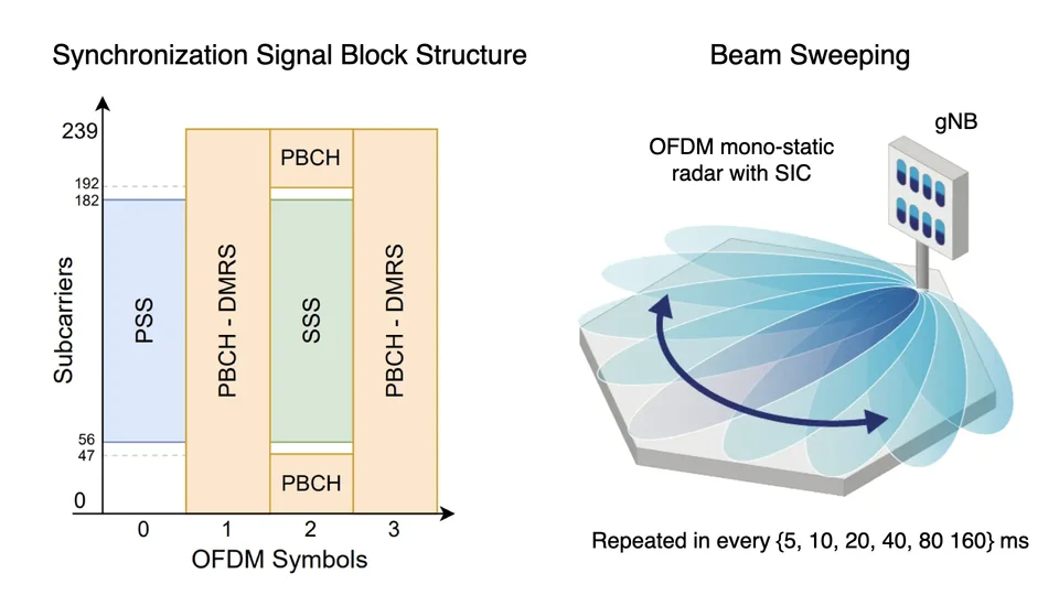
In the 5G standard, beam sweeping is typically periodically executed through exhaustive search methods to maintain continuous alignment of user equipment (UE) and base station (BS) beamformers. In a reconfigurable intelligent surface (RIS)-aided massive MIMO (mMIMO) system, beam training is a daunting challenge as RIS codebook sizes are significantly larger compared to regular transceivers. To address the beam-training overhead, deep learning-based solutions have attracted great interest, enabling learning from data and adapting to dynamic conditions. The integration of multimodal sensing offers enhanced capabilities by leveraging multiple data sources.
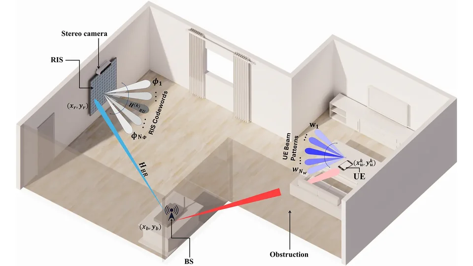
In this work, we present a deep reinforcement learning (DRL)-based beam selection framework aimed at maximizing the sum rate of a downlink multi-user (MU) RIS-aided mmWave mMIMO system, while satisfying quality of service (QoS) and fairness constraints. The beam selection process is supported by two key sensing modalities: 1) a stereo camera collocated at the RIS for detecting UEs, and 2) an inertial measurement unit (IMU) fitted at each UE to provide 3D Cartesian coordinates relative to their initial positions. A testbed was developed to validate the proposed framework.
DRL Algorithms
Double Deep Q-Network (DDQN)

Off-policy algorithm: Learns from past experiences stored in a replay buffer.
Critic-only structure: Prediction network to select the best action and a target network that stabilizes training.
Action space: Discrete.
Proximal Policy Optimization (PPO)

On-policy algorithm: Learns from only the current policy’s experiences.
Actor-critic structure: Actor (policy network) to select action and critic (value network) to evaluate the action.
Action space: Can be discrete or continuous.
Hardware Description
The RIS array houses 400 elements, arranged in a 20 × 20 grid. The total array size is chosen relative to the wavelength at 27.5 GHz, which is within the mmWave 5G n527 and n528 bands, and is equal to 77 × 77 mm², approximating to 7.1λ × 7.1λ. The RIS codebook is designed to direct incoming beams at angles ranging from 0° to 90°. An ESP-WROOM-32 module controls the RIS, allowing it to communicate with the central control unit (CCU) serially. A ZED 2 stereo camera is collocated with the RIS, including a pretrained YOLOv8 model that processes snapshots into coordinates.
The BS is fitted with an EVK02004 phased array antenna module connected to a signal generator. This phased array includes a 4 × 4 integrated uniform planar array (UPA) patch antenna connected to a radio frequency integrated circuit. The signal generator delivers continuous superimposed non-orthogonal multiple access (NOMA) signals with adjustable output power. The transmit beamformer is fixed, chosen from the 2D angle-based beam steering codebook.
Each UE is equipped with an identical EVK02004 phased array antenna module as the BS, connected to a USRP x310 platform that houses two 40 MHz UBX daughterboards and a Xilinx Kintex-7 FPGA, mounted on top of a robotic rover. At each time step, the rover moves within a quarter-circle area with no line-of-sight to the BS, due to an obstruction in the path, at distances dm ∈ [3, 5] meters from the RIS and at angles 𝜗m ∈ [0°, 70°], ∀ m ∈ {1, 2}. An IMU module is attached to the UE for position tracking. At each time step, the IMU provides (x, y, z) coordinates for the UE, with the snapshot taken by the stereo camera at the RIS simultaneously.
The CCU is a laptop that connects all the testbed components, including the BS, RIS, and stereo camera. This is done to facilitate synchronization and signal processing, as well as control signaling across the entire system.
Experimental Parameters
| Symbol | Definition | Value |
|---|---|---|
| PT | Max transmit power | 20 dBm |
| fc | Carrier frequency | 28 GHz |
| B | System bandwidth | 40 MHz |
| NS | Number of RIS elements | 400 |
| dBS | Distance between BS and RIS | 3 m |
| 𝜗BS | Angle between BS and RIS | −30° |
| dm | Distance between UEm and RIS | 3 to 5 m |
| 𝜗m | Angle between UEm and RIS | 0° to 70° |
Watch Our Presentation
How to download/use the Dataset
- You can download the dataset from the following link: Coming Soon
- You can download the code from the following link: Coming Soon
- How to use the dataset and Python code: Coming Soon
Copyright
The data and results presented in this work are protected by copyright and may only be used with proper citation. Any use of this work should reference the following papers: