Digital Twin For Indoor Scenario
Overview
In indoor wireless scenarios, Digital Twin enables the accurate modeling of complex environments, such as offices, factories, and smart homes, allowing for the real-time optimization of coverage, interference management, and seamless connectivity for IoT devices. IT supports applications like intelligent building management, immersive AR/VR, and industrial automation. At CCSL, we investigate two specific indoor DT scenarios: digital twin–aided beamforming design and digital twin–aided blockage prediction/detection for MIMO systems.
Experiment Description
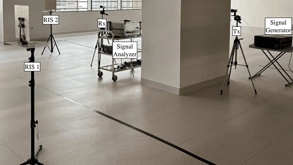
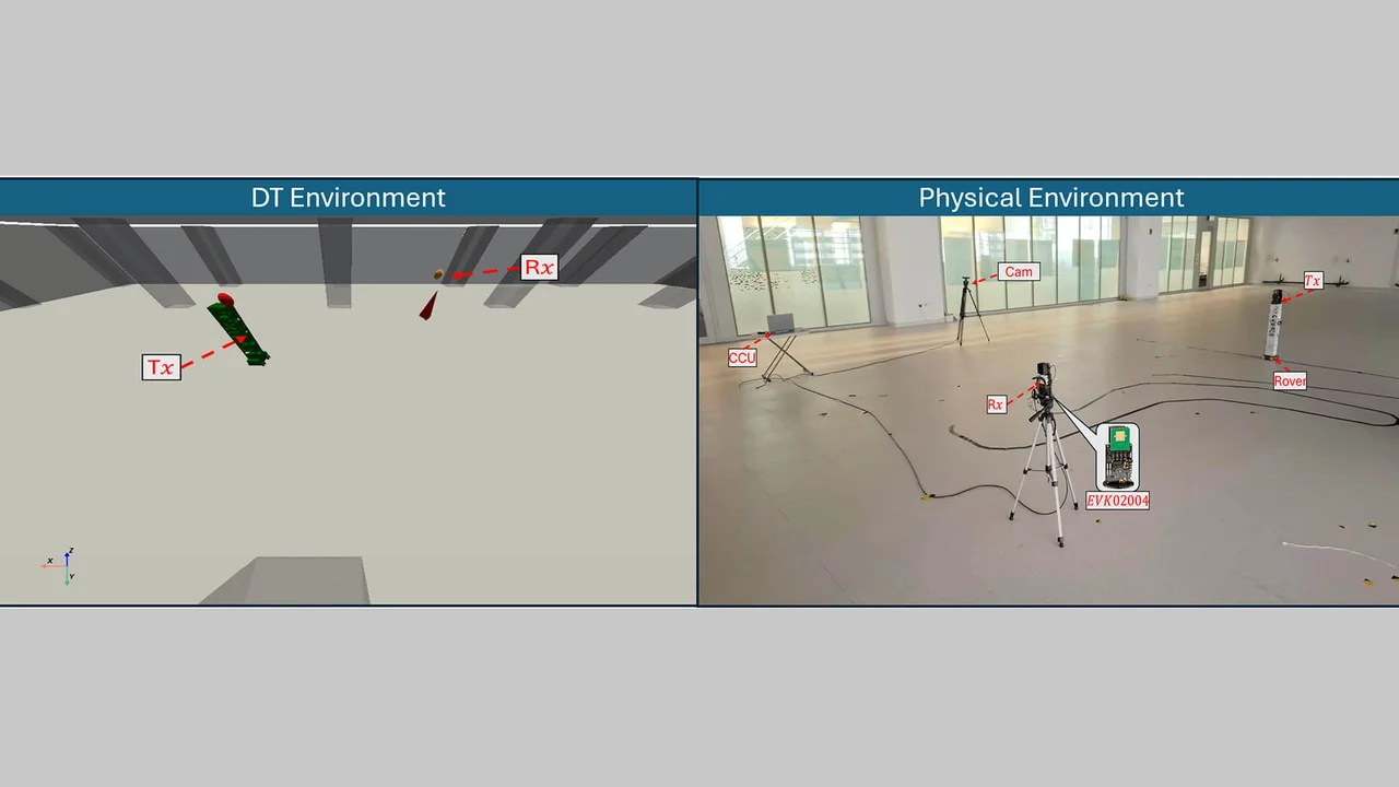
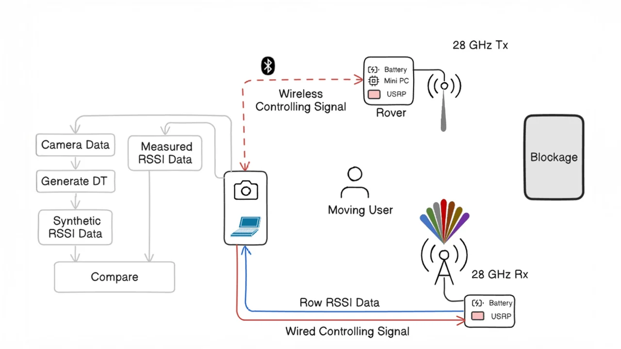
Digital Twin (DT) technology enables the precise modeling of complex indoor wireless environments, supporting real-time optimization of coverage and enhancing reliability, efficiency, and adaptability across diverse communication scenarios. In this work, we focus on two specific indoor DT applications: (i) digital twin–aided beamforming design for MIMO systems, and (ii) digital twin–aided blockage prediction and detection in cellular networks. To achieve this, a high-fidelity 3D model of our laboratory is constructed, serving as an accurate digital replica of the physical environment (Fig. 1). The experimental setup consists of one mmWave transmitter (TX) and receiver (RX) deployed in the lab as illustrated in Fig. 2. Received signal strength indicator (RSSI) measurements are collected from the hardware testbed and systematically compared with the RSSI values generated using a ray-tracing program applied to the 3D digital twin model. This comparison enables the validation of the DT framework and provides insights into its capability to predict wireless channel behavior under varying conditions, paving the way for intelligent, real-time adaptive communication strategies.
Hardware Description
- The TX employs an EVK02004 phased array antenna (Link) module with a 4×4 UPA patch array operating at 28 GHz, supporting a 64-codeword that steers beams from –45° to 45° in both azimuth and elevation. The phased array is connected to a USRP-200 Mini SDR (Link) for data transmission, controlled via a mini PC. The TX is mounted on a robotic rover and linked to the central control unit (CCU) through Bluetooth.
- The RX uses the same EVK02004 phased array antenna, connected to a USRP-200 Mini SDR for RSSI reception, and communicates with the CCU via USB for data processing.
- A ZED 2 (Link) stereo camera is integrated into the system for object detection and depth estimation, enabling the mapping of equipment positions and movement objects into the 3D digital twin model of the lab.
- The CCU, implemented on a workstation laptop, coordinates all components, manages control signaling, and performs synchronization and signal processing across the testbed.
Indoor Scenario 1
In this indoor scenario, the RX is fixed in position while the TX, mounted on a robotic rover, moves around it. The TX continuously transmits at 0° azimuth and 0° elevation, while the RX performs a beam sweep across azimuth angles from –45° to 45°, maintaining the same elevation as the TX. For each position of the rover, the received RSSI values from all beam directions are measured and reported to the CCU. A ZED 2 stereo camera, placed at a fixed location, tracks the rover’s movement in real time and reports its 3D coordinates (x, y, z) to the CCU. These measurements are mapped to the 3D digital twin of the lab, which is then passed to a ray-tracing program to generate synthetic RSSI values based on the modeled propagation environment. The CCU compares the measured RSSI from the real testbed with the synthetic RSSI obtained from the digital twin. Experimental results demonstrate that the difference between the real and synthetic RSSI values is typically less than 1 dBm, highlighting the accuracy of the digital twin model. Furthermore, analysis of the beam sweep patterns shows that the maximum beam direction predicted by the digital twin matches the actual measurements in more than 95% of the rover’s positions. These results confirm the effectiveness of digital twin technology in supporting beamforming design and prediction for MIMO systems, paving the way for intelligent and adaptive wireless communication strategies in complex indoor environments.
Indoor Scenario 2
In this indoor scenario, both the TX and RX remain fixed in position while a person moves dynamically between them. The TX continuously transmits at 0° azimuth and 0° elevation, while the RX performs a beam sweep across azimuth angles ranging from –45° to 45°, maintaining the same elevation alignment with the TX. For each sweep, the received RSSI values across all beam directions are recorded and transmitted to the CCU. A ZED 2 stereo camera, positioned at a fixed location, simultaneously tracks the person’s motion in real time, extracting the 3D coordinates (x, y, z) and reporting them to the CCU. These coordinates are mapped onto the 3D digital twin of the lab, which is subsequently used by a ray-tracing program to generate synthetic RSSI values based on the modeled propagation environment. The CCU then compares the actual RSSI measured in the physical testbed with the synthetic RSSI predicted by the digital twin. Results show that the discrepancy between the two measurements is generally less than 1 dBm, validating the accuracy of the digital twin model. Importantly, when the person passes between the TX and RX, creating a line-of-sight blockage, the received power experiences a sharp drop, an effect clearly captured in both the real measurements and the digital twin predictions. These findings demonstrate the capability of digital twin technology to effectively replicate and anticipate blockage events, confirming its value for applications such as blockage prediction and detection.
How to download/use the Dataset
- You can download the data set from the following link: Coming Soon
- You can download the code set from the following link: Coming Soon
- How to use the dataset and Python code: Coming Soon
Copyright
The data and results presented in this work are protected by copyright and may only be used with proper citation. Any use of this work should reference the following papers: